Expert Introduction
The author is a Principal Interconnect Engineer with over fifteen years of experience at leading manufacturers including TE Connectivity and Amphenol Corporation. He holds a Master of Science in Materials Engineering from the University of Illinois at Urbana-Champaign and holds six patents related to contact design and plating technologies. He currently serves on the IPC WHMA-A-620 standards committee and regularly consults for aerospace, medical device, and electric vehicle manufacturers. His failure analysis work has resolved over two hundred field reliability issues across global programs, and this article draws directly from that hands-on engineering experience.
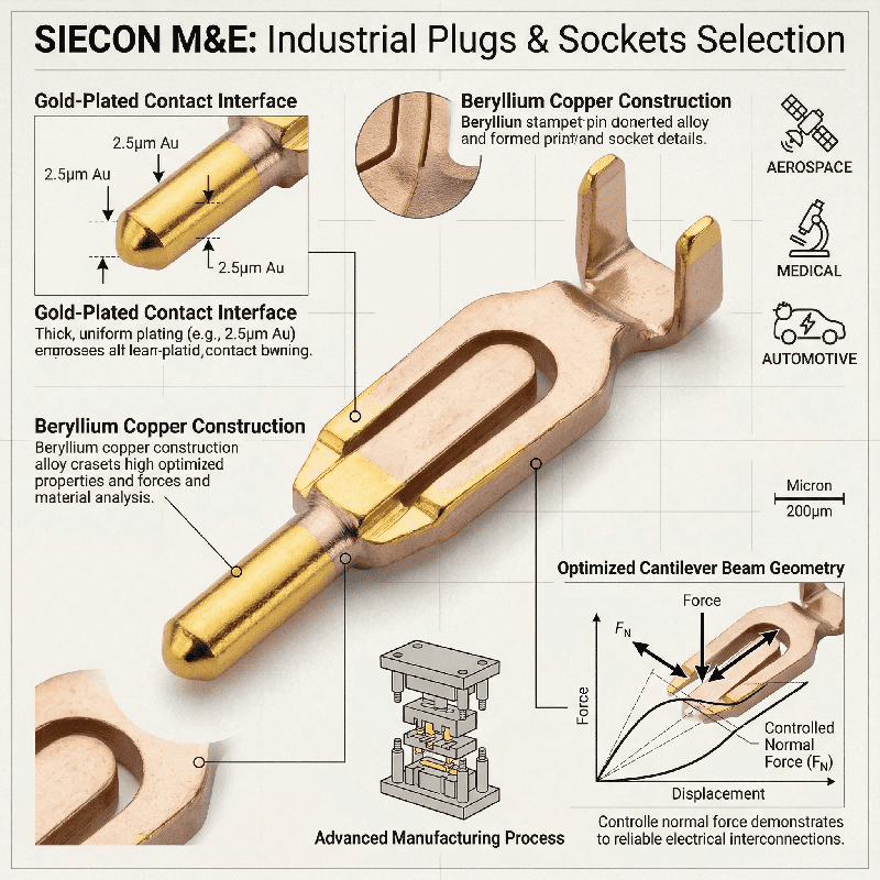
The Critical Role of Contact Normal Force
Contact normal force represents the most fundamental parameter governing socket pin reliability, as this force maintains the perpendicular pressure holding mating surfaces together at the interface. Insufficient normal force allows micro-motion fretting corrosion to destroy the electrical path over time, while excessive normal force complicates insertion and stresses the housing material beyond its limits. Industry standards typically specify a range between fifty and two hundred grams per contact, and achieving this balance requires precise control over the beam design and base material. Phosphor bronze and beryllium copper remain the dominant choices due to their excellent yield strength, with beryllium copper offering superior stress relaxation resistance at elevated temperatures reaching one hundred fifty degrees Celsius.
Case Study: Medical Device Intermittent Failure
I recall a specific case where a medical device manufacturer experienced intermittent failures after six months of use in a continuous patient monitoring system. Our investigation revealed that the socket pin’s normal force had dropped below thirty grams due to improper alloy selection, as the original design used a low-cost brass alloy that relaxed significantly under continuous thermal load. The operating temperature inside the device caused the brass to lose its mechanical spring properties, leading to micro-motions that created insulating oxides at the contact interface. Replacing the contacts with beryllium copper versions immediately resolved the intermittent connectivity issue, underscoring how material science directly dictates long-term mechanical stability.
Plating Strategies for Corrosion and Wear
Gold plating remains the gold standard for high-reliability socket pin applications in demanding environments, as the precious metal provides a noble surface that resists oxidation and maintains low contact resistance. However, gold plating thickness must be carefully matched to the expected mating cycle count, with thin layers under thirty microinches wearing through after as few as fifty cycles. Thicker plating of fifty to one hundred microinches supports thousands of insertion and withdrawal cycles, while nickel underplating serves a critical function as a diffusion barrier between gold and the base metal. Without this barrier, copper from the substrate migrates through microscopic pores in the gold layer, leading to resistive oxides that degrade electrical performance.
Case Study: High-Speed Data Signal Loss
I personally worked on a high-speed data application where intermittent signal loss plagued the system, and failure analysis revealed that the socket pin’s nickel underplate was only five microinches thick. Copper had diffused through the thin gold layer to reach the contact surface, forming copper oxide at the interface and causing resistance spikes during data transmission. Switching to a specification of fifty microinches of nickel underplate with thirty microinches of gold solved the issue completely, reinforcing the importance of specifying plating stacks as complete material systems. Selective plating strategies also help balance performance with cost by placing precious metal only where the socket pin actually contacts its mating terminal.
Mechanical Design for Beam Integrity
The geometry of the socket pin’s cantilever beam determines how it will perform over its service life, as stamped and formed contacts rely on careful radius design to avoid stress concentration points. Sharp corners in bend regions create local strain that accelerates material fatigue under cyclic loading, making finite element analysis an indispensable tool for optimizing beam designs. I have used FEA extensively to simulate insertion forces, stress distribution, and relaxation behavior for countless designs, with one particularly challenging project involving a socket pin for an automotive engine control module. The application required withstanding two thousand hours of thermal cycling from minus forty to one hundred twenty-five degrees Celsius, and initial prototypes exhibited cracking at the beam base after just five hundred cycles.
Case Study: Automotive Thermal Cycling Failure
FEA modeling identified a stress concentration caused by an overly aggressive bend radius, which created localized plastic deformation during each thermal cycle. Modifying the tooling to increase the radius eliminated the cracking entirely, and the redesigned socket pin passed full qualification with no further failures. This case demonstrates how simulation tools prevent costly field failures when applied early in development, as dual-beam and box-type contacts offer increased reliability by providing redundant current paths. These designs maintain contact force even if one beam experiences partial relaxation, though engineers must weigh these trade-offs based on the specific demands of each application.
Case Study: High-Vibration Aerospace Application
A prominent aerospace contractor approached my team with a critical avionics interconnect failure, as their flight control system was experiencing random disconnects during vibration testing on a new platform. The existing socket pin design had passed standard mil-spec vibration profiles for decades, but the new platform introduced higher-frequency vibrations in the two thousand hertz range that traditional contact designs were not optimized to handle. We initiated systematic root cause analysis using high-speed video microscopy and electrical monitoring, observing that the socket pin was experiencing momentary separations during specific resonant frequencies. The contact’s natural frequency aligned with the excitation frequency, causing dynamic unloading and temporary loss of electrical contact.
Aerospace Solution and Validation
Our solution involved shortening the beam length to raise the resonant frequency above the excitation range, while also increasing normal force from one hundred to one hundred fifty grams per contact. These modifications required requalifying the entire connector assembly for all performance parameters, and after three rounds of prototyping the new socket pin design passed all test requirements. The platform successfully entered service with zero reported interconnect failures in that subsystem, highlighting the importance of understanding dynamic mechanical behavior in socket pin design. Static analysis alone is insufficient when the end application involves complex vibration environments, and engineers must validate designs under actual application conditions.
Advanced Manufacturing and Quality Control
Precision manufacturing processes determine whether a socket pin design achieves its theoretical performance, as high-speed stamping presses can produce millions of contacts per day with remarkable consistency. However, tool wear over time can gradually alter critical dimensions like beam height and radius, which is why statistical process control systems monitor these parameters in real time during production runs. I have implemented SPC programs that automatically reject any socket pin exceeding specified control limits, while secondary operations such as coining and selective plating add further complexity to the manufacturing flow. Coining creates a defined contact surface by flattening a specific area of the beam, ensuring consistent mating interface geometry across millions of produced contacts.
Case Study: Plating Thickness Failure
One of my previous employers experienced a plating thickness variation that escaped normal sampling plans, resulting in a batch of socket pins with insufficient gold thickness reaching final assembly for a medical device. The resulting field failures cost over two million dollars in warranty claims and reputational damage, leading to the implementation of continuous XRF monitoring on every stamping line. That incident demonstrated that quality assurance must be viewed as an integral part of manufacturing rather than a separate inspection step, as continuous monitoring prevents escapes and protects brand reputation. Automated optical inspection systems now provide one hundred percent verification of critical dimensions, ensuring every socket pin meets the specified requirements before leaving the facility.
Material Selection for Extreme Environments
Emerging applications in electric vehicles and renewable energy push socket pin technology to new limits, as underhood temperatures in hybrid vehicles can exceed one hundred seventy degrees Celsius continuously. Standard polymer housings may not maintain their mechanical properties at such elevated temperatures, which is why high-temperature thermoplastics like LCP and PPS are now specified for these demanding environments. The socket pin itself must withstand prolonged exposure without significant loss of mechanical properties, with nickel-cobalt alloys such as MP35N offering exceptional strength and corrosion resistance for extreme conditions. These superalloys maintain their spring characteristics at temperatures where beryllium copper would relax, making them ideal for the most demanding applications.
Case Study: High-Cycle Battery Application
I recently consulted on a battery management system requiring ten thousand mating cycles in a dusty environment, where standard tin-plated socket pins failed due to fretting corrosion accelerated by particulate contamination. We specified a design using palladium-nickel plating with a gold flash for enhanced wear resistance, and the contact geometry was modified to incorporate a self-cleaning wiping action during each mating. This combination achieved over fifteen thousand cycles without any resistance increase beyond specification, demonstrating that such solutions require close collaboration between material scientists and mechanical design engineers. The trend toward higher power density will continue to drive innovation in contact materials and coatings, requiring engineers to stay current with emerging material technologies.
Verification and Validation Methodologies
Qualifying a socket pin design requires a comprehensive suite of environmental and mechanical tests, including contact resistance testing under thermal cycling to reveal how materials behave under realistic operating conditions. Dynamic testing while applying vibration and shock forces uncovers intermittent failures hidden in static measurements, while durability testing establishes the expected lifecycle by repeatedly mating and unmating the connector. Mixed flowing gas testing exposes contacts to controlled corrosive atmospheres to simulate years of aging, and I have managed qualification programs that cost over five hundred thousand dollars for a single connector family. Each test is designed to accelerate failure mechanisms that would otherwise take years to manifest, and the data generated informs derating guidelines that help end users apply the connector safely.
Case Study: Current Rating Overestimation
For one industrial control application, we discovered that the socket pin’s current rating was overly optimistic, as the original five amperes per contact led to excessive temperature rise in dense connector configurations. Further testing established a de-rated limit of three amperes when using all contacts simultaneously, and this derating information was added to the product datasheet to prevent field failures. Proper validation requires testing the socket pin within the full connector assembly and application environment, as test fixtures that do not replicate real-world conditions can produce misleading positive results. Engineers must always validate their designs under the most extreme conditions expected in service, ensuring that verification is not complete until all environmental factors are addressed.
Future Directions in Socket Pin Technology
The electronics industry continues to demand smaller, more reliable, and higher-current socket pin solutions, with miniaturization trends pushing contact spacing below one millimeter while maintaining robust performance. New manufacturing techniques like micro-stamping and selective laser melting enable unprecedented geometries, while additive manufacturing allows for complex beam shapes that were previously impossible to produce. Digital twins incorporating real-time field data will enable predictive maintenance for critical interconnects, and I anticipate significant advances in coating technologies that eliminate precious metals entirely. Graphene and other carbon-based materials show promise as solid lubricants and oxidation barriers, offering potential alternatives to traditional gold plating.
Smart Connectors and Integrated Sensing
The integration of sensors directly into socket pins will enable self-monitoring smart connectors that can detect force degradation or temperature anomalies before failure occurs. My current research focuses on embedding thin-film strain gauges within the contact beam structure, allowing systems to monitor normal force continuously throughout the product lifecycle. Such innovations will transform connectors from passive components into active monitoring devices, yet the fundamental physics of contact interfaces remains unchanged even as packaging evolves. Understanding those principles will always separate successful designs from field failures, and engineers who master socket pin fundamentals will remain indispensable in this rapidly advancing field.