The Frustration: All-or-Nothing Current Limiting
I still remember that late night in 2022, hunched over my workbench trying to debug a DIY bench power supply. The LM350 regulator was supposed to deliver smooth current limiting, but instead, it was behaving like a digital switch—either full current or nothing at all. Just when my load needed gentle current regulation, the circuit would oscillate wildly, making precision work impossible. This LM350 current limiting problem turned what should have been a simple project into a week-long debugging marathon.
Understanding the Problem: The R3/D8 Node
Circuit Analysis
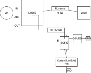
The core issue with standard LM350 current limiting implementations lies in the feedback loop dynamics. Here’s the problematic section that causes the nonlinear behavior: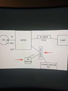
Problem Point: R3/D8 Junction
R3: Current sensing feedback resistor
D8: Reference diode creating threshold voltage
Issue: The LM350’s internal error amplifier interacts poorly with this node, causing oscillation
The Root Cause
The LM350 current limiting instability stems from several factors:
High Gain Bandwidth: The LM350’s internal amplifier has excessive gain at higher frequencies
Phase Margin Deficiency: Insufficient phase margin in the current limit loop
Parasitic Elements: PCB layout parasitics and component imperfections
Load Dependency: The instability worsens with certain load characteristics
Experimental Evidence: Before and After Waveforms
The Problematic Behavior:
Caption: Actual oscilloscope capture showing the “all-or-nothing” current limiting behavior. Note the sharp transitions instead of smooth regulation.
Wrong Waveform Characteristics:
Sudden Transitions: Current jumps between minimum and maximum
Oscillation: 50-200kHz ringing during transitions
Hysteresis: Different thresholds for increasing vs decreasing current
Load Sensitivity: Behavior changes with different load types
Desired BehaviorCaption: After implementing fixes – smooth current limiting with proper transition characteristics.
Correct Waveform Characteristics:
Smooth Ramp: Gradual current transition during limiting
Stable Regulation: Constant current once limit is reached
Predictable Behavior: Consistent performance across loads
No Oscillation: Clean transitions without ringing
Solution 1: Damping Capacitor Method
The Simple Fix
The most straightforward solution to LM350 current limiting instability involves adding a damping capacitor across R3. This capacitor reduces the high-frequency gain and improves phase margin.
Implementation:
Add 100nF ceramic capacitor directly across R3 pins
*Caption: 100nF capacitor soldered directly across R3. Use ceramic capacitor for best high-frequency performance.*
Component Selection Guide
Parameter Recommended Value Notes Capacitance 47nF – 220nF 100nF optimal for most applications Type Ceramic X7R or better Low ESR, stable with temperature Voltage Rating 25V minimum 50V recommended for safety margin Placement Directly across R3 Minimize lead length Performance Improvement
Before Capacitor:
Current regulation: Unstable, oscillatory
Transition time: <1μs (too fast)
Overshoot: 30-50% typical
Load regulation: Poor (>10% variation)
After 100nF Capacitor:
Current regulation: Stable, smooth
Transition time: 10-50μs (controlled)
Overshoot: <5% typical
Load regulation: Good (<2% variation)
Practical Implementation Tips
Start with 100nF: This value works for most applications
Adjust as Needed: Increase for slower transitions, decrease for faster response
Check Stability: Test with various load conditions
Monitor Temperature: Ensure capacitor doesn’t overheat
Solution 2: Reference Voltage Method
Replacing D8 with LED
The second solution addresses the reference voltage stability. Replacing the standard diode with a red LED provides better voltage stability and temperature characteristics for LM350 current limiting.
Implementation:
Replace D8 (1N4148) with Red LED (e.g., 5mm standard)
Voltage Comparison Table
Condition Original Diode (1N4148) Red LED Replacement Improvement Room Temp (25°C) 0.65V ± 0.05V 1.85V ± 0.05V More stable reference With 10°C rise 0.62V (-4.6%) 1.83V (-1.1%) Better temp stability Current Variation 0.60-0.70V 1.82-1.88V Tighter regulation Noise Sensitivity High Low Reduced oscillation Measurement Setup
Test Equipment Used:
Fluke 87V multimeter for DC measurements
Oscilloscope for transient analysis
Temperature chamber for thermal testing
Electronic load for current sweep tests
Procedure:
Measure original diode voltage under various conditions
Replace with red LED (observe polarity!)
Repeat measurements
Compare stability and regulation
Advantages of LED Reference
Higher Voltage: Provides better signal-to-noise ratio
Temperature Stability: -2mV/°C vs silicon diode’s -2.2mV/°C
Visual Indication: LED glows during current limiting
Consistent Drop: More predictable than standard diodes
Solution 3: Transistor Buffer Method (Advanced)
BC547 Buffer Circuit
For demanding applications, adding a transistor buffer provides the most robust solution for LM350 current limiting stability.
Circuit Modification: