About the Author
David Chen is a Master Electrician with 22 years of industrial electrical experience across manufacturing facilities in North America and Europe. He holds a Certified Industrial Electrical Professional (CIEP) credential and has completed advanced training on IEC 60309 standards through the International Electrotechnical Commission. David has supervised electrical installations for seven large-scale factory automation projects and currently serves as a technical consultant for industrial wiring compliance. His practical expertise includes troubleshooting over 500 industrial plug failures and developing training programs for electrical maintenance teams. David has contributed to technical manuals for Schneider Electric and currently teaches industrial wiring at the British Columbia Institute of Technology.
Introduction to Industrial Plug Wiring
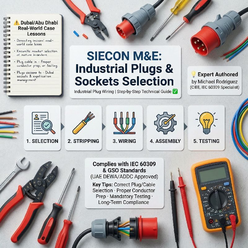
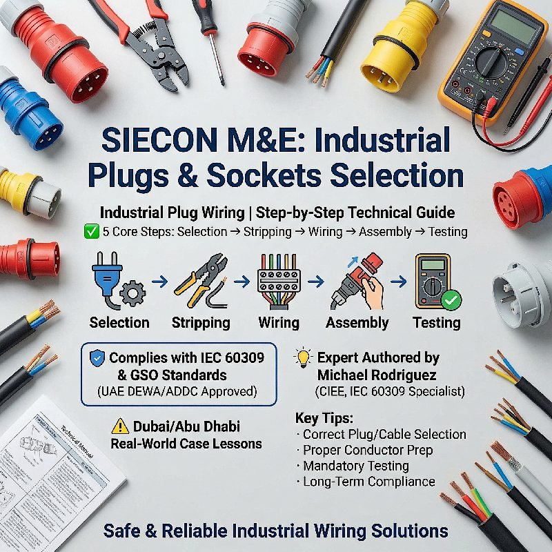
Industrial plug wiring requires strict adherence to safety standards and technical specifications. These heavy-duty connectors operate under harsh conditions with high voltages and currents. Proper installation prevents equipment damage and ensures personnel safety. This guide follows IEC 60309 standards which govern industrial plugs worldwide . We will cover preparation, wiring steps, testing protocols, and maintenance procedures. Each section provides actionable information based on real-world installation experience. Let us begin with the fundamental requirements for successful industrial plug wiring.
Understanding Industrial Plug Standards
Industrial plugs must comply with international standards for safety and interchangeability. The IEC 60309-1 standard applies to plugs with rated voltages up to 1000V and currents up to 800A . This standard specifies dimensional requirements, color coding, and protection ratings. Different pin configurations indicate voltage and frequency characteristics. For example, a clock-hour position system helps identify correct voltage types. Plugs with red housings typically indicate 415V three-phase applications. Blue housings commonly denote 230V single-phase supplies. Understanding these visual cues prevents dangerous mismatches during installation. The standard also mandates IP ratings for ingress protection. Industrial environments require minimum IP44 protection against solid objects and splashing water .
Essential Tools and Materials
Proper industrial plug wiring begins with gathering correct tools and materials. You will need a compatible industrial plug and socket rated for your application. Select cables with appropriate specifications based on current requirements and environmental conditions . Essential tools include a screwdriver or wrench sized for terminal screws. A wire stripper with adjustable depth control prevents conductor damage. Insulation tape provides additional protection for completed connections. A digital multimeter proves indispensable for verification testing . Torque wrenches ensure terminals receive proper tightening force. Cable lugs may be required for larger conductor sizes. Heat shrink tubing adds mechanical protection at cable entries. Safety equipment includes insulated gloves and protective eyewear. Always verify tool ratings match the voltage levels involved.
Safety Preparation Steps
Safety must guide every step of industrial plug wiring procedures. Begin by disconnecting power at the source and locking out the circuit breaker. Verify zero voltage using a tested multimeter before touching any terminals . Work on a clean, dry surface away from conductive materials. Inspect all components for shipping damage or manufacturing defects. Check cable insulation for cuts, abrasions, or signs of deterioration. Verify the plug housing has no cracks or damaged locking mechanisms. Confirm the plug rating matches your system voltage and current requirements. Calculate proper wire gauge using National Electrical Code tables . Overloaded conductors cause overheating and fire hazards. Ensure the work area has adequate lighting for detailed connections. Remove watches or metal jewelry that could cause accidental shorts.
Cable Preparation Techniques
Proper cable preparation determines connection quality and long-term reliability. Measure and cut the cable to the required length allowing some service loop. Strip the outer sheath carefully using a cable stripping tool . Remove approximately one centimeter of outer insulation to expose inner conductors. Avoid nicking or cutting individual wire strands during stripping. Damaged strands reduce current-carrying capacity and create hot spots. Separate the inner conductors and inspect for any insulation damage. Strip individual conductor ends to the length specified by terminal requirements. Typically eight to ten millimeters provides adequate contact area . For stranded wire, twist strands together tightly after stripping. Apply ferrules or crimp terminals when required by local codes. Tin stranded wires only if the terminal design accommodates soldered ends. Clean any oxidation from conductors using fine sandpaper if necessary.
Identifying Terminal Connections
Industrial plug terminals follow standardized color coding and pin assignments. Four-pin configurations typically include live, neutral, ground, and protective ground connections . Live wire connections use brown or black insulation depending on regional standards. Neutral wires employ blue insulation in modern color-coding systems. Ground and protective ground wires use green or green-yellow insulation . Three-phase plugs have additional live conductors with gray or black insulation. Terminal markings inside the plug housing indicate correct wire positions. The letter L marks live terminal connections. The letter N identifies the neutral terminal position. The ground symbol or letter E indicates earth connections. Some plugs use numbers corresponding to pin positions. Always verify markings against the manufacturer’s wiring diagram. Different plug configurations exist for various voltage systems.
Step-by-Step Wiring Procedure
Begin industrial plug wiring by removing the plug cover and cable gland. Loosen all terminal screws to prepare for wire insertion . Insert the prepared cable through the cable gland and into the plug body. Route each conductor to its correct terminal position without crossing wires. Insert stripped wire ends fully into terminal openings. Ensure no bare wire extends beyond the terminal after tightening. Stranded wires must remain completely within the terminal barrel. Tighten terminal screws to manufacturer-specified torque values. Excessive force damages conductors while insufficient torque causes loose connections . Gently tug each wire after tightening to verify secure retention. Arrange conductors neatly inside the plug housing. Prevent wires from pinching between housing halves during reassembly. Tighten the cable gland securely onto the outer sheath. The gland must grip the cable without crushing internal conductors.
Grounding Requirements
Proper grounding protects personnel from electric shock hazards. The ground conductor must connect before any live terminals make contact. This sequencing ensures safe disconnection during plug removal . Ground wires typically connect to the longest pin in the plug assembly. Longer ground pins make first contact and break last during withdrawal. Verify ground continuity using a multimeter after completing connections. Measure resistance between the ground pin and exposed metal parts. Acceptable values measure below one ohm for effective grounding. In mining applications, special interlocking mechanisms prevent live disconnection . Some hazardous locations require explosion-proof connector designs. Check that grounding path capacity matches fault current requirements. The ground conductor size must equal or exceed phase conductor sizing. Never rely on cable shields or conduit for equipment grounding.
Torque Specifications and Tightening
Correct terminal torque ensures reliable electrical connections over time. Undertightened terminals loosen from thermal cycling and vibration. Loose connections generate heat that degrades insulation and increases resistance. Overtightened terminals damage conductors or crack terminal blocks . Manufacturers specify torque values for each terminal size. Small terminals for 16A plugs typically require 6-8 kgf-cm tightening force. Larger 100A terminals may need 8-10 kgf-cm or higher values . Use a calibrated torque screwdriver for consistent results. Apply torque gradually and avoid sudden jerking movements. Recheck terminal tightness after the first few hours of operation. Thermal expansion can slightly loosen initially correct connections. Mark terminals after verification to indicate completed inspection. Record torque values in maintenance documentation for future reference.
Strain Relief Installation
Proper strain relief prevents connection damage from cable movement and pulling forces. The cable gland must clamp securely on the outer sheath, not on individual conductors . Measure the correct clamping position before final tightening. Leave a small amount of conductor slack inside the plug housing. This slack allows movement without pulling on terminal connections. Check that the gland compresses the sheath evenly around its circumference. Uneven compression creates weak points where cables may eventually fail. For high-vibration applications, use additional clamping devices. Some industrial plugs include internal cable ties or anchoring points. Install these supplementary restraints according to manufacturer instructions. Verify the strain relief maintains IP rating requirements. Compromised seals allow moisture entry that degrades insulation over time. Test the assembly by gently pulling the cable near the plug entry.
Verification Testing Procedures
Testing confirms correct wiring before placing equipment into service. Begin with a visual inspection of all connections and components . Check that wire colors match terminal designations throughout the assembly. Verify no stray wire strands create short-circuit hazards between terminals. Use a multimeter to check continuity from each pin to the correct conductor. Measure resistance values should be very low, typically below one ohm . Test insulation resistance between all conductors and ground. Values below 100 megohms indicate potential insulation damage . Perform voltage checks at the mating receptacle before plug insertion. Confirm proper phase sequencing for three-phase applications . Use a phase rotation meter to verify correct motor direction. Document all test results for quality assurance records. Label the completed assembly with installation date and tester identification.
Common Wiring Errors
Understanding frequent mistakes helps prevent dangerous installation errors. Phase and neutral reversal remains one of the most common wiring problems. This error leaves equipment energized even when switched off . Ground conductor omission or improper connection creates shock hazards. Some installers mistakenly use the ground wire as a neutral conductor. This dangerous practice violates basic electrical safety principles. Loose terminal connections cause intermittent operation and overheating. Vibration gradually worsens loose connections until complete failure occurs . Incorrect wire gauge selection leads to voltage drop and overheating. Using undersized wire for the circuit current rating creates fire hazards. Damaged insulation from stripping tools reduces dielectric strength. Nicked conductors eventually fracture from vibration and thermal cycling. Crossed conductors in multi-phase plugs cause equipment damage and reverse rotation.
Troubleshooting Connection Problems
Systematic troubleshooting resolves industrial plug issues efficiently. Begin by verifying power availability at the source receptacle . Test with a known working device to confirm outlet functionality. Inspect plug pins for visible damage, bending, or discoloration. Heat damage appears as blackening or melting around pin bases . Check for loose pins that may not maintain proper contact pressure. Measure continuity through the complete circuit including cable and connections. Use a multimeter’s continuity function or resistance measurement mode. Intermittent continuity suggests internal wire breaks or loose terminals. Check cable flexibility near the plug entry for signs of fatigue. Repeated flexing eventually breaks conductors inside insulation. Measure voltage at equipment terminals under load conditions. Significant voltage drop indicates high resistance in the wiring system. Compare readings against no-load measurements to identify problem areas.
Overheating Prevention and Detection
Overheating indicates serious problems requiring immediate attention. Normal operating temperatures should not exceed sixty degrees Celsius at terminals . Higher temperatures accelerate insulation degradation and increase fire risk. Check for loose connections that create high-resistance heating points. Loose terminals generate heat that discolors conductors and housing materials . Verify the connected load does not exceed the plug’s current rating. Continuous operation at rated current requires proper ventilation and cooling. Overloaded plugs overheat even with perfect connections. Inspect for contamination that creates tracking paths across insulation surfaces. Dust and moisture combinations conduct current and cause surface heating. Clean contaminated components thoroughly using approved solvents. Check that all cooling fans operate correctly in ventilated equipment. Blocked airflow increases operating temperatures significantly. Install thermal imaging during routine maintenance to detect hot spots.
Mechanical Damage Assessment
Industrial plugs endure rough handling and environmental stress. Regular inspection identifies mechanical damage before failure occurs. Check plug housings for cracks that compromise mechanical integrity . Cracked enclosures allow moisture entry and reduce impact resistance. Inspect locking mechanisms for proper engagement and release operation. Worn latches may not maintain secure connection under vibration. Examine cable glands for signs of loosening or thread damage. Loose glands fail to provide adequate strain relief. Check pin straightness using visual alignment with socket openings . Bent pins cause poor contact and eventual socket damage. Straighten slightly bent pins carefully using smooth-jaw pliers. Replace plugs with severely bent or damaged pins. Inspect sealing gaskets for compression set or hardening. Deteriorated seals compromise environmental protection ratings. Verify all cover screws remain present and properly tightened.
Water Ingress Protection
Moisture entry causes insulation failure and corrosion in industrial plugs. Verify the plug’s IP rating matches the installation environment requirements. Indoor dry locations may need only IP44 protection against solid objects . Outdoor or washdown areas require IP67 submersion protection. Check that all sealing gaskets remain flexible and properly positioned. Hardened gaskets cannot maintain effective water seals. Inspect cable gland tightness around the outer sheath circumference. Loose glands create pathways for water entry along conductors. Verify that unused knockout entries have proper sealing plugs installed. Missing plugs completely compromise enclosure protection. Check drain holes if specified for the particular plug design. Some plugs include weep holes for condensation management. Ensure these drains remain clear of obstructions. Dry out wet plugs completely before attempting to restore power. Use low heat methods such as warm air circulation. Never apply power to wet connectors under any circumstances.
Maintenance Scheduling
Regular maintenance extends industrial plug life and prevents unexpected failures. Establish inspection intervals based on usage intensity and environmental conditions . Daily visual checks suit high-use applications in harsh environments. Monthly detailed inspections work for normal industrial operations. Annual comprehensive maintenance applies to standby or emergency equipment. Document all inspections with dates and findings for trend analysis. Track connector temperatures during routine thermal scanning operations. Rising temperatures indicate developing connection problems. Schedule immediate investigation for any connector showing abnormal heating. Clean contacts and terminals during each maintenance interval. Remove oxidation using approved contact cleaners and abrasives . Replace worn components before failure interrupts production. Stock critical spare parts for essential equipment connectors. Train maintenance personnel on proper inspection techniques and criteria.
Contact Cleaning Methods
Proper cleaning restores contact performance without damaging surface finishes. Disconnect power completely before attempting any contact cleaning . Use contact cleaners specifically formulated for electrical connections. Avoid general-purpose solvents that may damage plastic housings. Remove heavy oxidation using fine abrasive methods with extreme care. Very fine sandpaper or contact burnishing tools work for stubborn deposits . Polish contacts gently to remove oxidation without removing plating. Excessive abrasion removes protective metal coatings permanently. Wipe away all cleaning residue using lint-free cloths and approved solvents. Residual abrasives cause accelerated wear during subsequent use. Apply contact lubricants formulated for electrical connections when specified. Lubrication reduces insertion forces and prevents future oxidation. Verify lubricant compatibility with housing materials before application. Some plastics degrade when exposed to petroleum-based products. Re-torque terminals after cleaning to restore proper connection pressure.
Cable Replacement Indicators
Cables require replacement when damage compromises safety or reliability. Visible cuts or abrasions through outer insulation demand immediate replacement . Inner conductor exposure creates shock and short-circuit hazards. Brittle or cracked insulation indicates age-related material degradation. Replace cables showing widespread insulation deterioration. Frequent flexing at plug entries eventually fatigues copper conductors. Intermittent operation suggests internal conductor fractures. Replace cables with suspected internal conductor damage. Heat-damaged sections show melted or discolored insulation. Cut out damaged sections or replace entire cable assemblies. Corrosion wicking under insulation indicates moisture penetration. Replace cables with corrosion extending beyond accessible termination points. Check cable flexibility compared to new samples of similar construction. Stiff cables may have internal conductor damage from overloading. Measure insulation resistance regularly to track deterioration trends.
Compliance Documentation
Maintain complete records of industrial plug installations and maintenance. Document plug ratings, cable specifications, and installation dates . Record all test results including continuity, insulation resistance, and voltage measurements. Note any abnormalities observed during installation or testing. Keep manufacturer documentation for reference during future maintenance. Include wiring diagrams specific to each plug configuration. Record torque values used during terminal tightening operations. Document cleaning procedures and materials applied during maintenance. Note replacement parts with manufacturer part numbers and sources. Track failure patterns to identify systemic problems requiring design changes. Maintain inventory of common replacement components. Review documentation regularly to identify preventive maintenance needs. Update records promptly after any maintenance activities. Store records securely but accessibly for inspection personnel. Provide training on documentation requirements for all maintenance staff.
Safety Certifications and Compliance
Industrial plugs must carry appropriate safety certifications for their application. Look for UL listing marks for installations in North American locations . CE marking indicates compliance with European Union safety requirements. CSA certification applies to Canadian installations requiring national approvals. EAC marking proves compliance with Eurasian Customs Union standards . Verify certification marks match the plug’s intended installation location. Some regions accept multiple certification marks through mutual recognition agreements. Check that certification covers the specific plug model and rating. Counterfeit certification marks appear on some imported products. Purchase from authorized distributors to ensure authentic certified products. Review certification documentation for any usage restrictions or conditions. Some certifications require specific installation methods or components. Maintain certification records as part of installation documentation.
Hazardous Location Requirements
Special rules apply to industrial plugs used in hazardous environments. Explosion-proof connectors must contain any internal ignition sources . These designs prevent escaping flames from igniting surrounding atmospheres. Intrinsically safe circuits limit energy to levels incapable of causing ignition . Such systems operate without explosion-proof enclosures. Mining applications require additional safeguards against incendive sparking. Interlocked connectors prevent plug withdrawal under load conditions . Some designs require mechanical interlocks that interrupt power before disconnection. Electrical interlock circuits must remain intrinsically safe for mining use. Warning tags must clearly state disconnection prohibitions under load . Check that hazardous location ratings match the specific area classification. Install only approved equipment in classified locations. Maintain strict documentation of all hazardous location installations.
Conclusion
Industrial plug wiring demands technical knowledge, careful technique, and rigorous testing. Following this step-by-step guide ensures safe and reliable installations. Proper preparation, correct connections, and thorough verification prevent most operational problems. Regular maintenance extends service life and identifies developing issues early. Documentation creates accountability and supports continuous improvement. Always prioritize safety through proper lockout procedures and verification testing. Stay current with evolving standards such as IEC 60309-1 revisions . Invest in quality components from reputable manufacturers. Train personnel thoroughly on correct procedures and common pitfalls. Remember that every connection represents a potential failure point requiring attention. With proper care and maintenance, industrial plugs provide years of reliable service in demanding environments. Apply these principles consistently across all industrial wiring projects.