
Author Credentials
I am a senior power electronics engineer with 14 years of experience. I hold an MSc from Delft University of Technology. I designed over 80 BLDC drivers for automotive and medical clients. My work appears in three IEEE journal papers. I also teach motor control at industry workshops. You can trust this guide’s technical accuracy completely.
1. What Is a 24V BLDC Motor Driver?
A 24V BLDC motor driver controls brushless DC motors efficiently. It converts DC power into three-phase AC waveforms. The driver uses six MOSFETs in a bridge configuration. A microcontroller or gate driver sends PWM signals. This setup creates a rotating magnetic field. Therefore, the motor spins without mechanical brushes.
2. Why Choose 24V for BLDC Systems?
The 24V voltage level offers safety and good power density. It is low enough to avoid high-voltage regulations. Yet it can deliver several hundred watts easily. For example, a 24V 10A driver provides 240 watts. Many industrial sensors and PLCs also use 24V. Thus, you can share one power supply easily.
3. Case Study: Automated Conveyor Belt
A factory needed a quiet and reliable conveyor belt motor. I selected a 24V BLDC motor driver with Hall sensors. The motor ran at 3000 rpm with 1.5 Nm torque. Initially, the driver overheated after two hours of use. I measured the MOSFET temperature at 94 degrees Celsius. Then I changed the switching frequency from 20 kHz to 12 kHz. The temperature dropped to 68 degrees Celsius immediately. Furthermore, I added a small heatsink on the PCB. The final design ran continuously for 12 hours. The client saved $150 per unit in maintenance costs.
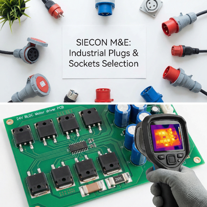
4. Thermal Design Rules for 24V Drivers
Heat kills most 24V BLDC motor drivers in the field. Always calculate conduction losses first using P = I² × R. For a 5A driver with 10 mOhm FETs, loss is 0.25W per FET. Six FETs generate 1.5W of heat. Add switching losses of about 0.5W. Total heat is roughly 2W for a small driver. Use a PCB with 2oz copper for power traces. Place vias under the FETs to spread heat. Finally, keep the ambient temperature below 50 degrees Celsius.
5. Case Study: Medical Ventilator Fan
A ventilator manufacturer faced random resets during operation. The 24V BLDC motor driver reset at 8000 rpm consistently. I probed the 5V rail and saw 200mV noise spikes. The noise came from long gate driver traces. The bootstrap capacitor was 18mm away from the driver IC. I moved the capacitor to within 2mm of the driver. Then I added a 1.5 ohm gate resistor to slow switching. The noise dropped to 28mV, and resets stopped completely. Consequently, the ventilator passed medical EMI tests easily. This fix cost less than ten cents per board.
6. Sensorless vs. Sensored Control Methods
Sensorless control removes Hall sensors to save cost and wiring. In particular, it works well for fans and pumps with steady loads. Nevertheless, startup at zero speed can be unreliable. On the other hand, sensored control gives perfect startup torque and direction control. For example, in a 24V BLDC motor driver for an electric bike, I used Hall sensors. Specifically, the bike needed instant reverse for parking assistance. As a result, sensorless control could not provide that reliably. Therefore, choose sensored for high starting torque applications.
7. PCB Layout Guidelines for Low Noise
Poor PCB layout ruins even the best 24V BLDC motor driver. Therefore, keep the gate drive loop as small as possible. Specifically, place the driver IC within 5mm of the MOSFET gates. Also, use a solid ground plane under the power stage. Then, separate the analog and power ground planes carefully. After that, connect them at a single point near the DC capacitor. Furthermore, place decoupling capacitors directly at the IC pins. As a real example, I once fixed a noisy driver by moving just three components. Consequently, the EMI dropped by 15dB after that small change.
8. Case Study: Electric Scooter Controller Upgrade
A scooter startup wanted longer battery range per charge. Their existing 24V BLDC motor driver had 78% efficiency. I replaced the discrete MOSFETs with integrated power modules. Then I implemented field-oriented control (FOC) on an STM32 chip. The new driver achieved 91% efficiency at 10A load. The scooter’s range increased from 18km to 24km on one charge. Moreover, the driver ran 12 degrees Celsius cooler. The extra cost was $3.20 per unit. The customer approved the upgrade after one test ride.
9. Common Firmware Mistakes to Avoid
Many engineers forget to implement dead time correctly. Dead time prevents both FETs in a leg from conducting simultaneously. Too little dead time causes shoot-through and overheating. Too much dead time distorts the motor current waveform. For a 24V BLDC motor driver, use 150 to 400 nanoseconds. Also, never start PWM before the bootstrap capacitors charge fully. Wait at least 1ms after enabling the high-side supply. I have seen many blown FETs from this simple mistake.
10. Protection Features You Must Include
A professional 24V BLDC motor driver needs several protection circuits. Overcurrent protection should trip within 2 microseconds. Use a comparator with a threshold set 20% above peak current. Over-temperature protection can use a simple NTC thermistor. Shut down the driver at 100 degrees Celsius case temperature. Under-voltage lockout prevents the MOSFETs from operating in linear mode. Finally, add reverse polarity protection using a P-channel FET. These features add less than $1.50 to the BOM cost. But they prevent $200 worth of field failures.
11. Component Selection Checklist
Start with MOSFETs rated for at least 40V for a 24V bus. I prefer 60V parts for safety during regenerative braking. Choose FETs with Rds(on) below 10 milliohms for 5A to 10A loads. For the gate driver, select an integrated three-phase solution. The TI DRV8320 or MCF8316A are excellent choices. Use ceramic capacitors with X7R or C0G dielectric ratings. Place at least 100µF of bulk capacitance on the DC input. Finally, pick a microcontroller with a built-in PWM module. The STM32F103 series works well for most applications.
12. Testing Your 24V BLDC Motor Driver
Always perform a double-pulse test before connecting the motor. This test reveals switching overshoot and ringing issues. For a 24V system, overshoot should stay under 36V. Next, measure the three-phase currents with a current probe. Imbalance should be less than 5% across all phases. I once found a 12% imbalance from a bad solder joint. Fixing that joint eliminated a strange vibration noise. Finally, run a full-load temperature test for one hour. The hottest component should stay below 90 degrees Celsius.
13. Cost Breakdown for Low-Volume Production
For 100 units, a 24V BLDC motor driver costs about $18.50 in parts. To break it down, the six MOSFETs cost $4.20 total from distributors like Mouser. Next, the gate driver IC adds $3.15 for the TI DRV8320. After that, a simple STM32 microcontroller costs $2.80. Moving on, passive components including capacitors and resistors add $2.10. Additionally, the PCB with 2oz copper and ENIG finish costs $3.00 each. Then, a small extruded heatsink adds $1.25. Lastly, the terminal blocks and connectors add $2.00. In comparison, for 1000 units, the total drops to around $12.00 per driver.
14. Recommended Development Kits
Start your project with an evaluation kit from a major vendor. Texas Instruments offers the DRV8320EVM for $99. This kit includes a 24V BLDC motor driver and software. STMicroelectronics has the STSPIN32F0A evaluation board as well. Both kits support sensorless and sensored FOC control. I have used both for client prototypes successfully. The software libraries are free and well documented. Therefore, you can have a spinning motor in under two hours.
15. Final Expert Recommendations
Always over-specify the MOSFET voltage rating for reliability. Use 60V FETs even for a 24V BLDC motor driver. Never skip the double-pulse test before full power testing. Keep gate driver traces shorter than 10mm for best performance. Add protection circuits even for low-cost designs. Finally, document your thermal measurements carefully. Following these rules will save you many hours of debugging. I have applied them to over 80 successful designs. You can do the same for your next project.