About the Author
Michael Torres is a Licensed Master Electrician with 24 years of field experience specializing in industrial and commercial electrical installations. He holds certifications from the National Electrical Contractors Association (NECA) and completed advanced training in concrete embedding techniques through the American Concrete Institute. Michael has supervised electrical rough-ins for over 45 major construction projects including manufacturing plants, distribution centers, and infrastructure developments across the United States. His hands-on expertise includes installing more than 3,500 industrial sockets in poured concrete, precast panels, and concrete block walls. Michael currently serves as a senior technical instructor for the International Brotherhood of Electrical Workers (IBEW) and contributes regularly to industry publications on masonry electrical installation methods. He has developed code-compliant training programs adopted by electrical apprenticeship schools in five states.
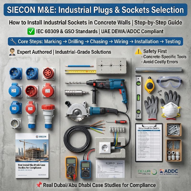
Introduction to Industrial Socket Installation
Installing industrial sockets in concrete walls demands precision and technical knowledge. Concrete presents unique challenges including density variations and reinforcement placement. Proper installation ensures reliable power distribution and long-term safety. This guide follows National Electrical Code (NEC) requirements and industry best practices. We cover everything from planning and drilling to sealing and testing. Each section provides actionable steps based on proven field techniques. The methods described apply to poured concrete, precast panels, and concrete masonry units. Let us begin with essential preparation and safety considerations.
Understanding Concrete Wall Types
Concrete wall construction varies significantly across industrial facilities. Poured concrete walls offer uniform density but may contain rebar reinforcement. Precast concrete panels arrive pre-formed with smooth or textured surfaces . Concrete block walls have hollow cores that require special anchoring techniques . Each type demands specific installation approaches for industrial sockets. Poured concrete accepts expansion anchors and concrete screws reliably. Precast panels require careful drilling to avoid surface spalling. Block walls need masonry anchors placed in solid web areas. Understanding your wall type determines tool selection and anchoring method. Older concrete may contain aggregate that affects drilling performance. Reinforcement location should be verified before marking cutouts.
Safety Preparations and Code Compliance
Safety must guide every step of industrial socket installation. Verify that all circuits are de-energized before beginning work. Use lockout-tagout procedures to prevent accidental re-energization . Wear appropriate personal protective equipment including safety glasses. Concrete dust contains silica requiring respiratory protection during cutting. Hearing protection is essential when using hammer drills and rotary hammers. Check local codes for concrete embedding requirements before starting. NEC Article 314 outlines box installation requirements for masonry . Some jurisdictions prohibit certain conduit types embedded in concrete . Verify that industrial socket boxes meet UL requirements for wet locations if applicable. Confirm that the installation location provides adequate working space per code. Document all code approvals for inspection purposes.
Selecting the Right Industrial Socket Box
Box selection directly impacts installation success and long-term reliability. Metal boxes provide superior strength for concrete embedding applications . Galvanized steel resists corrosion from concrete moisture during curing. Cast iron boxes offer maximum durability for heavy industrial use. PVC boxes cost less but may deform during concrete placement . Gray PVC boxes designed for exterior use perform better than standard blue boxes . Industrial socket boxes require adequate cubic inch capacity for wire fill. Deep boxes accommodate larger conductors and easier pulling. Weatherproof boxes with gasketed covers suit outdoor concrete wall installations . Select boxes with multiple knockout options for conduit entry flexibility. Verify that the box rating matches the intended environment and application.
Tools and Materials Required
Professional installation requires specific tools designed for masonry work. A rotary hammer with SDS bits penetrates concrete efficiently . Standard hammer drills work for smaller holes in lighter applications. Masonry bits must match anchor diameter and embedment depth precisely. Vacuum attachments control silica dust during drilling operations. A level ensures industrial sockets mount straight on wall surfaces. Torque wrench confirms proper anchor tension without over-tightening. Wire strippers prepare conductors for terminal connections. Cable cutters handle larger industrial feeder sizes. Materials include concrete screws or expansion anchors rated for pull-out values. Tapcon screws work well for lighter industrial socket applications . Sleeve anchors provide higher holding strength for heavy boxes. Threaded rod with concrete adhesive suits embedded mounting applications. Weatherproof sealant prevents moisture penetration at box edges. Silicone caulk fills gaps between box and concrete surface.
Marking and Layout Procedures
Accurate layout ensures professional appearance and code-compliant positioning. Measure mounting heights according to industrial standards for equipment type. Typical receptacle height for industrial applications ranges from 12 to 18 inches . Switch boxes generally mount 48 inches to center from finished floor. Use a level to establish horizontal alignment between multiple boxes. Mark box outline on concrete surface using pencil or marker. Transfer mounting hole locations accurately using box as template. Verify that marked positions avoid known reinforcement locations. Check that spacing between multiple industrial sockets meets code minimums. Consider equipment placement when determining horizontal positions. Allow adequate clearance for plug insertion and cord routing. Document layout measurements for inspection and future reference. Double-check all marks before proceeding to drilling.
Drilling Techniques for Concrete Walls
Drilling concrete correctly prevents blowouts and ensures secure anchoring. Start with a pilot hole using smaller bit when precise location matters. Drill to depth marked on bit using tape depth gauge . Maintain perpendicular alignment to wall surface throughout drilling. Clear dust periodically by withdrawing bit during drilling. Let the tool do the work without applying excessive pressure. Overheating dulls bits quickly and damages concrete. Stop immediately if bit contacts reinforcement steel. Relocate box slightly when rebar prevents proper drilling. Blow dust from holes using compressed air or vacuum. Clean holes thoroughly before installing anchors. Debris prevents anchors from achieving full holding strength. Use vacuum attachments to control airborne silica dust. Allow motor to cool between holes in dense concrete.
Anchor Types and Selection Criteria
Anchor selection must match load requirements and concrete conditions. Sleeve anchors provide reliable holding power for industrial socket boxes . Wedge anchors suit heavy-duty applications in solid concrete. Tapcon concrete screws work well for lighter boxes and frequent adjustments . Hammer drive anchors offer quick installation for permanent mounting . Chemical adhesive anchors excel in cracked concrete or vibration-prone areas. Each anchor type has specific embedment depth requirements. Pull-out values vary significantly between anchor designs and sizes. Check manufacturer specifications for rated loads in your concrete type. Larger anchors require larger holes and greater edge distance. Consider future removal needs when selecting permanent anchors. Stainless steel anchors resist corrosion in outdoor or wet locations. Zinc-plated carbon steel suits interior dry environments. Match anchor material to box material to prevent galvanic corrosion.
Installing Masonry Anchors Properly
Proper anchor installation determines long-term holding strength. Insert anchor through box mounting hole into concrete opening. Tap anchor gently until washer and nut contact box surface. Tighten nut to manufacturer-specified torque using calibrated wrench . Undertorqued anchors loosen over time from vibration. Overtorqued anchors may strip threads or crack concrete. Concrete screws require driving with care to prevent cam-out. Sleeve anchors expand as nut tightens against concrete. Ensure expansion sleeve positions completely within solid concrete. Wedge anchors need torque applied gradually for proper setting. Chemical anchors require mixing and curing time before loading. Follow all manufacturer instructions for adhesive cure duration. Test each anchor after installation by gentle tugging. Loose anchors must be removed and replaced properly.
Securing Industrial Socket Boxes
Box mounting must be rigid and flush with finished wall surface. Position box against concrete with anchors through mounting holes. Tighten all anchors evenly to pull box flush against wall. Box should not rock or move when pressure applied . Flush mounting prevents gaps that collect moisture and debris. Recessed boxes may require box extensions for code compliance. Surface-mounted boxes attach directly to concrete without recessing. Verify vertical alignment using level before final tightening. Adjust as needed during anchor seating process. Some industrial boxes include integral mounting flanges . Others require external mounting brackets or strut supports. Heavy boxes may need additional support from threaded rod. Consider using backing materials for irregular concrete surfaces . Apply corrosion protection where box contacts concrete directly.
Conduit Entry and Connections
Conduit connections must maintain integrity throughout concrete contact. Rigid metal conduit suits embedded applications best . Intermediate metal conduit provides acceptable strength for most uses. EMT requires careful sealing to prevent concrete entry . PVC conduit works but may deform during concrete placement. Use threaded fittings for maximum reliability in concrete. Watertight fittings prevent moisture migration into boxes. Apply conduit sealants at all threaded connections. Support conduits adequately before concrete placement. Concrete pressure can displace unsupported conduits during pour. Running threads through boxes allows adjustment after concrete sets. Leave slack for final positioning during rough-in. Protect conduit openings from concrete entry during pour. Tape or plug openings temporarily until wiring installed.
Waterproofing and Sealing Methods
Outdoor industrial sockets demand complete weatherproof protection . Apply sealant around box perimeter where concrete meets metal . Use butyl rubber or polyurethane sealants rated for concrete adhesion. Fill all gaps completely to prevent water pathways. Seal conduit entry points using listed sealing fittings. Some installations require expansion foam for moisture barriers . Verify that box gaskets remain intact and properly seated. Weatherproof while-in-use covers protect plugged connections. Drip loops in wiring prevent water from following conductors . Grade sealant applications to shed water away from openings. Inspect seals annually and reapply as materials age. IP66-rated boxes provide additional protection where specified . Consider spray-on waterproofing for entire installation in wet areas.
Wiring Industrial Sockets
Wiring procedures must follow NEC requirements for industrial installations. Use conductors rated for wet locations when applicable . THWN-2 or XHHW-2 suits most outdoor concrete applications. Strip insulation carefully to avoid nicking copper strands. Connect ground wire first to ensure safety during installation. Wrap terminals clockwise around binding screws for proper contact. Torque terminal screws to manufacturer specifications. Maintain proper wire bending space inside industrial boxes. Avoid sharp bends that damage conductor insulation. Use wire connectors listed for conductor material and count. Label circuits clearly at panel and within junction boxes. Document wire colors and circuit assignments for future maintenance. Leave sufficient conductor length for future re-termination. Six inches of free conductor typically meets code requirements.
Grounding Requirements
Proper grounding protects personnel and equipment from faults. Metal boxes require equipment grounding conductor connection . Use green wire or bare copper for grounding purposes only. Install ground screw in tapped hole provided in metal boxes . Bond all metal boxes together with continuous grounding path. Verify ground continuity using multimeter after installation. Resistance values below one ohm indicate effective grounding. Concrete contact alone does not provide adequate equipment ground. Separate grounding electrode conductor may be required for some installations. Check local codes for additional grounding requirements. Industrial settings often demand enhanced grounding systems. Document ground resistance measurements for inspection records. Retest grounding after any modifications to installation.
GFCI Protection Requirements
Ground-fault protection saves lives in industrial environments. NEC requires GFCI protection for many receptacle locations. Outdoor industrial sockets typically need GFCI protection . Wet locations including concrete walls demand GFCI devices. Use GFCI circuit breakers for multiple receptacle protection. GFCI receptacles protect downstream outlets when wired properly. Test GFCI function monthly using integral test button. Verify trip time meets code requirements of 1/40 second. Document GFCI locations and test dates for compliance records. Replace GFCI devices that fail test procedures. Industrial settings may require specialized GFCI types for equipment. Combination GFCI and surge protection suits sensitive electronics.
Sealing Cable Entry Points
Cable entry points often leak when improperly sealed. Use IP-rated cable glands for each conductor entering box . Glands must match cable diameter for effective sealing. Multiple cables require multi-cable glands or separate entries. Apply sealant around gland threads and box openings. Verify that gland compression seals cable jacket properly. Leave drip loops before cable entry points . Seal unused knockouts with listed close-up plugs. Missing plugs completely compromise weatherproof integrity. Inspect seals periodically for cracking or separation. Replace damaged glands immediately to prevent water entry. Consider using duct seal for temporary sealing applications. Permanent installations require listed sealing methods.
Testing Installed Industrial Sockets
Thorough testing verifies correct installation before energizing. Perform visual inspection of all connections and components. Check polarity using receptacle tester for standard configurations. Measure voltage between hot and neutral at each outlet. Verify hot and ground voltage matches hot and neutral reading. Test ground impedance using ground resistance tester. Acceptable values measure below 25 ohms typically. Perform insulation resistance test on all wiring. Values below one megohm indicate potential insulation damage. Test GFCI trip function using integral and external testers. Document all test results for quality assurance records. Label each industrial socket with test date and inspector identification. Retain records for future maintenance reference.
Common Installation Errors
Avoid frequent mistakes that compromise industrial socket installations. Using plastic boxes in concrete applications risks deformation . Blue PVC boxes crush easily during concrete placement . Failing to seal conduit openings allows concrete blockage. Drilling too deep penetrates wall and creates leaks . Overtightening anchors cracks concrete around mounting holes. Undertightening allows box movement and connection stress. Incorrect anchor selection leads to premature failure. Ignoring rebar locations damages structure and tooling. Poor knockout preparation leaves sharp edges damaging wire. Skipping grounding creates serious shock hazards. Inadequate waterproofing causes corrosion and shorts. Rushing sealant application leaves gaps for moisture.
Troubleshooting Installation Problems
Systematic troubleshooting resolves common industrial socket issues. No power typically indicates tripped breaker or loose connection. Intermittent operation suggests loose termination or damaged wire. GFCI tripping repeatedly points to ground fault downstream. Warm outlets signal overloaded circuit or poor connections. Corroded terminals indicate moisture penetration requiring sealing. Difficult plug insertion suggests damaged receptacle contacts. Loose mounting results from failed anchors or overtightening. Cracked concrete around box indicates excessive torque or impact. Water inside box reveals failed seals or missing gaskets. Buzzing sounds suggest loose connections or failing device. Replace damaged components rather than attempting field repairs. Document all troubleshooting findings for pattern recognition.
Maintenance Requirements
Regular maintenance extends industrial socket service life significantly. Inspect outdoor installations quarterly for seal deterioration. Check gaskets for compression set or cracking . Retest GFCI function monthly per manufacturer recommendations. Verify cover plates remain intact and properly seated. Clean corrosion from exposed metal surfaces promptly. Reapply sealant at first signs of cracking or separation. Test ground continuity annually using appropriate meters. Document all maintenance activities for compliance records. Train personnel to report damage or unusual conditions. Schedule infrared scanning to detect hot connections. Replace worn receptacles before failure interrupts operations. Stock critical spare components for essential equipment.
Code Compliance and Documentation
Complete documentation supports code compliance and future modifications. Maintain as-built drawings showing industrial socket locations. Record circuit breaker assignments and panel schedules. Document wire types, sizes, and installation dates. Keep manufacturer cut sheets for all installed components. Note any code amendments or variances obtained. Retain inspection reports and approval certificates. Photograph installations before covering for hidden conditions. Update documentation whenever modifications occur. Store records securely but accessibly for maintenance personnel. Provide training on documentation requirements for staff. Review documentation annually to identify update needs. Digital records with cloud backup protect against loss.
Conclusion
Installing industrial sockets in concrete walls requires careful planning and execution. Proper tool selection, anchor choice, and sealing methods ensure reliable long-term performance. Following code requirements protects personnel and equipment from electrical hazards. Regular maintenance extends service life and prevents unexpected failures. Documentation creates accountability and supports future modifications. Always prioritize safety through proper lockout procedures and verification testing. Stay current with evolving NEC requirements affecting concrete installations. Invest in quality materials from reputable manufacturers. Train installation personnel thoroughly on correct procedures. Remember that concrete installations become permanent once cured. Apply these principles consistently across all industrial socket projects. With proper techniques, your installations will provide decades of reliable service in demanding environments.